
 EN
EN
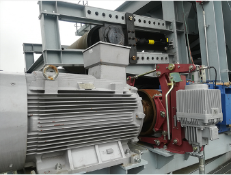
Mounting the Hydraulic Winch for Excavator: Structural Integrity and Compatibility
Frame compatibility and load-path analysis
Mounting a hydraulic winch for excavator begins with verifying frame compatibility—specifically matching the winch to the excavator’s class, boom geometry, and coupler interface. The frame must route pulling forces directly through the machine’s primary structural members, not secondary components like thin side plates or unqualified welds. A rigorous load-path analysis considers rope pull direction, drum fleet angle, and fairlead placement to minimize side loading and torsional stress. Critical design factors include base plate thickness (minimum 1¼" for mid-size machines), bolt grade (Grade 10.9 or higher), and full-penetration weld access. Even minor misalignment risks uneven rope spooling, accelerated drum flange wear, and fatigue cracking in brackets. Ensure the mount clears full boom articulation and attachment movement—interference compromises both safety and functionality. A well-engineered mount distributes static and dynamic loads evenly across the structure, preserving both winch integrity and excavator longevity.
Bracket alignment, bolt torque specifications, and reinforcement best practices
Bracket alignment must ensure the rope enters the drum within the manufacturer-recommended fleet angle—typically 1.5° to 2.5°—to prevent off-center spooling, premature wear, and reduced pulling capacity. Once aligned, tighten all mounting bolts to the torque values specified by the winch manufacturer using a calibrated torque wrench. Use high-strength bolts (Grade 10.9 or 12.9) with hardened washers to resist vibration-induced loosening. Where additional rigidity is needed, weld-on gussets or reinforcement plates may be added to the arm or quick coupler—but only after confirming clearance from hydraulic lines, sensors, and moving parts. Re-torque all fasteners after the first 2–4 hours of operation, then incorporate torque verification into daily pre-use inspections. Consistent alignment and secure fastening directly extend drum bearing life and prevent bracket deformation under cyclic loading.
Connecting the Hydraulic Winch for Excavator: Hoses, Fittings, and System Matching
Hose sizing, port compatibility, and ISO/JIC fitting standards
Hose sizing must align with both the excavator’s auxiliary hydraulic flow rate and the winch motor’s inlet requirements. Undersized hoses increase fluid velocity beyond the recommended 15–20 ft/s, leading to pressure drop, heat buildup, and premature seal degradation. For mid-range excavators (20–30 ton), hose inner diameter typically ranges from ½" to 1", matched precisely to the motor’s port size and flow demand. Port compatibility between the winch valve block and the machine’s auxiliary circuit is non-negotiable—many winch motors require a dedicated case drain line to prevent seal failure from excessive backpressure. Use ISO 6149 or JIC 37° flare fittings exclusively; their standardized sealing geometry and torque specs deliver reliable, leak-free connections. Route return lines to maintain backpressure below 300 PSI—exceeding this threshold delays brake release and accelerates fluid oxidation. Secure all fittings with correct torque and never mix thread types, as cross-threading remains a leading cause of field leaks and safety incidents.
Matching winch displacement to excavator hydraulic output (e.g., 40–60 GPM @ 3,000 PSI)
Optimal performance depends on matching the winch motor’s displacement to the excavator’s available flow and pressure. Machines in the 20-ton class commonly deliver 40–60 GPM at 3,000 PSI—values that define the winch’s torque output and line speed. Oversized displacement results in sluggish response and insufficient torque; undersized units risk overspeed, cavitation, and thermal overload. Calculate required torque using:
Torque (lb-ft) = (Pressure × Displacement) / (2π)
Then convert to line pull via drum radius. For example, a 2.5 cu in/rev motor operating at 3,000 PSI generates ~1,190 lb-ft of torque—translating to ~20,000 lb line pull on a 6-inch drum radius. The winch’s relief valve setting must also match the excavator’s system pressure to avoid unnecessary bypass and energy loss. Field data confirms properly sized units improve pulling efficiency by at least 25% compared to mismatched alternatives—reducing fuel consumption and extending component life.
Operating the Hydraulic Winch for Excavator Safely: Brake Control and Load Management
Safe operation hinges on two interdependent systems: fail-safe brake control and disciplined load management. Most hydraulic winches use a spring-applied, hydraulically released brake—engaging automatically upon pressure loss to hold loads without operator input. For controlled lowering, a properly sized counterbalance valve is essential to prevent runaway and absorb shock; field testing shows such valves reduce peak shock forces by up to 40%.
Key operational safeguards include:
- Verifying brake release pressure matches the excavator’s auxiliary output—mismatches cause delayed engagement or overheating.
- Using a dedicated load-holding valve block to regulate return line backpressure and ensure smooth, predictable motion. Excessive backpressure (>300 PSI) can impede full brake release, resulting in jerky starts and increased wear.
- Adhering strictly to rated line pull limits. Overloading risks structural failure, brake slip, and irreversible drum or cable damage—the brake must hold the full load without measurable creep.
- Conducting pre-operation checks: inspect wire rope for broken strands or corrosion, confirm drum grooving is uniform and free of sharp edges, and verify the fairlead guides rope centrally without side loading.
- Engaging emergency stop and electronic overload protection—these circuits cut hydraulic flow instantly if load exceeds preset thresholds.
According to the Lifting Equipment Engineers Association (LEEA), brake system failures accounted for 27% of winch-related incidents in 2022. Operators must test the brake under no-load conditions before each shift: center the control valve and confirm immediate, silent drum stoppage. Consistent adherence to these practices extends service life and maintains system reliability.
Maintaining the Hydraulic Winch for Excavator: Inspection, Cleaning, and Fluid Care
Cable Wear, Drum Grooving, Seal Integrity, and Contamination Checks
Daily wire rope inspection is non-negotiable. Examine the full length for broken wires, kinks, corrosion, or diameter reduction exceeding 3%—a definitive indicator of fatigue and imminent failure. Drum grooving must remain uniform; irregular wear promotes rope distortion, binding under load, and accelerated fatigue. Smooth any burrs or sharp edges after each operation. At gearbox and motor interfaces, inspect seals for cracking, extrusion, or leakage—moisture ingress compromises lubrication and invites internal corrosion. As SKF notes, even trace water contamination reduces oil’s load-carrying capacity by 30%. Conduct monthly fluid sampling for particle count, water content (<0.1%), and oxidation state using a patch test or portable analyzer. Prioritizing system cleanliness prevents abrasive wear in valves, pumps, and servo controls—often the root cause of unexplained pressure loss or erratic response.
Hydraulic Filter Replacement, Fluid Analysis, and Leak Diagnostics
Replace hydraulic filters every 500 operating hours—or sooner in dusty, high-contamination environments—using only manufacturer-specified elements with a beta rating ≥200. Fluid analysis provides early warning of internal wear: track iron and copper levels for gear and bearing degradation, and act when acid number exceeds 2.0 mg KOH/g, signaling advanced fluid breakdown (Eaton, 2023). Leak diagnostics require methodical execution: first visually inspect all fittings, hoses, and cylinder rods for wetness or residue; then perform a pressure-decay test to identify internal bypass in valves or motor housings. Even a minor external leak—one drop per second—wastes over 300 liters of fluid annually and can erode system pressure by up to 15%, directly reducing pulling capacity. Address leaks immediately—not just for efficiency, but to prevent air entrainment, which accelerates oxidation and causes erratic valve operation.
FAQ
Q1: What factors should I consider when mounting a hydraulic winch on an excavator?
A1: Key factors include ensuring frame compatibility with the excavator’s class, performing proper load-path analysis to minimize stress, maintaining alignment, and choosing bolts and welds that meet the necessary standards.
Q2: How do I ensure proper hydraulic hose and fitting connections?
A2: Ensure hose sizing aligns with hydraulic flow rate requirements, maintain port compatibility, and use ISO or JIC fittings for leak-proof connections.
Q3: How can I maintain safe operations with the hydraulic winch?
A3: Follow safety protocols including using a fail-safe brake system, monitoring brake release pressure, adhering to line pull limits, and conducting pre-operation checks.
Q4: How frequently should hydraulic filters be replaced?
A4: Hydraulic filters should generally be replaced every 500 operating hours or earlier if working in dusty environments.
Q5: What maintenance steps are critical for extending the life of a hydraulic winch?
A5: Regular wire rope inspections, drum grooving maintenance, seal checks, fluid sampling, and addressing leaks and contaminants are essential for longevity and reliability.
Table of Contents
- Mounting the Hydraulic Winch for Excavator: Structural Integrity and Compatibility
- Connecting the Hydraulic Winch for Excavator: Hoses, Fittings, and System Matching
- Operating the Hydraulic Winch for Excavator Safely: Brake Control and Load Management
- Maintaining the Hydraulic Winch for Excavator: Inspection, Cleaning, and Fluid Care
- FAQ