עקרונות יסודיים של מערכות רכבת תחבורה הידראולית
הגדרה ותפקיד רכבת תחבורה הידראולית
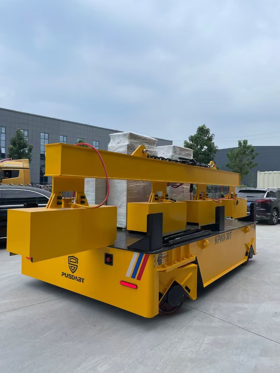
רכבי העברה הידראוליים הם בעיקר מכונות גדולות המשמשות להעברת מטענים כבדים מאוד ברחבי רצפות מפעלים או לאורך מסילות. הם פועלים על ידי דחיקת נוזל תחת לחץ כדי לדחוף מטענים ענקיים ממיקום אחד לאחר. תעשייה כמו ייצור פלדה, קווי הרכבה אוטומotive ומכרות מתכות סומכות עליהם רבות, מאחר ואין שום דבר אחר שיכול להתמודד עם העברת מספר טונות של חומרים בדיוק גבוה בין חלקים שונים בתהליך הייצור. בהשוואה לשיטות ידניות ישנות או למערכות מכניות חלשות יותר, יחידות הידראוליות אלו מקטינות את העצירות ושמורות על פעילות חלקה במהלך היום ללא הפרעות מתמידות.
חוק פסקל ומדעי תמסורת הספק נוזלי
רכבים הידראוליים פועלים על בסיס משהו שנקרא חוק פסקל. בעיקרון, כאשר מופעל לחץ על נוזל הכלוא, הוא מתפשט באופן אחיד בכל כיוון. זהו מה שעושה אותם כל כך עוצמתיים בתזוזת דברים. לדוגמה, חישבו על יישום של כ-500 psi למבעבר שגודלו בערך 10 אינץ' רבוע. התוצאה? נוצרת כוח דחיפה של כ-5,000 ponds היורד ישר דרך המערכת. מחקרים שנבדקו כיצד מערכות הידראוליות מעבירות אנרגיה מגלים מדוע מערכות אלו מנצחות בקלות את החשמליות כשמדובר בהשגת טורק גדול במעטפת קטנה. בתנאים קיצוניים בהם נדרשת כמות גדולה של כוח, מנועים הידראוליים יכולים לספק עד 60 אחוז ביצועים טובים יותר מאלו החשמליים, למרות שהם קטנים בהרבה בגודלם.
אי-דחיסות של נוזלי הידראוליקה וכفاءת המערכת
הדחיסות הקרובה לאפס של שמן הידראולי מבטיחה איבודי אנרגיה מינימליים במהלך העברת כוח. בניגוד למערכות ניאומטיות, שמבוזבזות אנרגיה בהדחת אוויר, מערכות הידראוליות מגיעות ליעילות של 85–92% (מכון ההספק הזורם, 2023). זה מאפשר מיקום מדויק של עומסים בדיוק של ±2 מ"מ, גם כשנשאו סלילי פלדה של 50 טון או תבניות יציקה.
שילוב רכיבים הידראוליים בעיצוב רכבות תמורה
רכבות תמורה מודרניות משולבות ארבעה רכיבים הידראוליים מרכזיים:
- משאבות בוכנה צירית הופכות אנרגיה מכנית ללחץ זורם (עד 5,000 psi)
- מנועים הידראוליים צמד מספקים סיבוב סנכרוני של גלגלים
- שסתומי נגד-איזון מונעים תנועה לא מבוקרת במהלך עצירות חירום
- مبادלי חום קומפקטיים שימור צמיגות שמן אופטימלית
שילוב זה מפחית את עלויות התפעול ב-35% בהשוואה למערכות אלקטרו-מכניות, ומאריך את תוספי התחזוקה ליותר מ-2,000 שעות פעילות.
רכיבים מרכזיים של רכבת העברה הידראולית
משאבות הידראוליות ומנגנוני המרת אנרגיה
במהותן, משאבות הידראוליות פועלות ככוח העבודה המרכזי שהופך אנרגיה מכנית לכוח הידראולי מוחץ. השוק מציע מספר סוגים, ביניהם משאבות גלגל שיניים, משאבות פיסטון ומשאבות להט, כאשר כל אחת מתאימה לצרכים של לחץ מסוים. למשל, משאבות גלגל שיניים פועלות בדרך כלל סביב 3,000 PSI בתנאים נורמליים, לפי נתוני Texas Hydrostatics. אך כאשר המצב נעשה קיצוני יותר, נכנסות לשימוש משאבות פיסטון, המסוגלות לעמוד בלחצים הגבוהים בהרבה מ-6,000 PSI. לאחר שמתרחשת עליית הלחץ, מתחיל תהליך התנועה בתוך מערכת הנוזל החסומה. מומחים בתחום מכנים זאת ליבת הפעולה, שכן ללא עליית לחץ מתאימה, שום דבר אחר לא יעבוד כראוי.
מנועים הידראוליים לתנועה סיבובית ולבקרת הנעה
מנועים אלו הופכים את פעולת המשאבה, הממירים אנרגיה הידראולית חזרה לסיבוב מכני ליניעת גלגלים. תפוקת מומנט העולה על 10,000 נממא מאפשרת תנועה של משקלים של עד 50 טון ומעלה על פני רצפות מפעליות לא שטוחות. עיצובי זיזה משתנים מאפשרים בקרת מהירות מדויקת באמצעות שסתומי התאמת זרימה.
シילינדרים הידראוליים לתנועה קווית מדויקת
シילינדרים דו-פעלים מספקים כוח דחיפה בין 5 ל-500 טון בדיוק מיקום של ±2 מ"מ. מוטות נירוסטה וחיבורים מפוליאוריטן מבטיחים מחזורי הרמה והחזרה מהימנים גם בסביבות עמוסות שברירים. אורכי מחזור ניתנים להגדרה עד 6 מטרים, בהתאם לתפישות תעשייתיות שונות.
שסתומים, מיכלים, צינורות ובקרה של דינמיקת נוזלים
שסתומים לשליטה בכיוון מתאמים את מסלולי הזרימה עם זמני תגובה של 0.1 שניות, בעוד מסננים בגודל 50 מיקרון שומרים על תקני ניקיון נוזלים לפי ISO 4406 18/16/13. צינורות מפולימר תרמופלסטי מחוזק עמידים בדפקי לחץ של עד 5,000 PSI בטווח טמפרטורות של 40-°F עד 300°F. עיצובי מחיצות במיכלי איחסון מורידים את רמת הזיהום של הנוזל ב-70% בהשוואה למיכלים סטנדרטיים.
מערכות הידראוליות סגורות לעומת פתוחות
מערכות סגורות מחזירות 95% מנפח הנוזל, מה שהופך אותן לא lýelles להפעלה מתמדת ושינויי כיוון מהירים. תצורות פתוחות הן זולות יותר לשימוש בדיד, ודורשות מיכלים קטנים ב-40%. שילוב שלمبادלי חום הוא קריטי בעיצוב מערכות סגורות, כדי לשמור על טמפרטורת נוזל אופטימלית בין 120°F ל-140°F.
הנעת כוח ותנועה בקרשים הידראוליים
רכבות העברה הידראוליות ממירות אנרגיה מאוחסנת לתנועה מכנית מבוקרת באמצעות דינמיקה מדויקת של נוזלים. מערכות אלו מנצלות עקרונות פיזיקליים בסיסיים להעברת משאות כבדים בסביבות תעשייתיות קשות.
העברת כוח באמצעות לחץ הידראולי תוך שימוש בחוק פסקל
מערכות הידראוליות פועלות בהתאם לעיקרון שנקרא עקרון פסקל, שלפיו כאשר מופעל לחץ על נוזל חתום, הוא מועבר לאורך כל המערכת ללא איבוד כוח. זו הסיבה שמתקני העברה יכולים להגביר את הכוח שלהם בצורה דרמטית. למשל, משאבה סטנדרטית של 100 psi עלולה ליצור יותר מ-10,000 psi בהגדרת צילינדר נכונה. העובדה שהלחץ נשאר אחיד בכל המערכת אומרת שמכונות אלו מספקות עוצמה אמינה גם כשיש עקומים בדרכים או שינוי במשקולות מעבודה אחת לאחרת.
המרת אנרגיה הידראולית לתנועה ליניארית וסיבובית
משאבות ממירות אנרגיה מכנית לאנרגיית לחץ נוזל, בעוד שהמנועים עושים את ההפך – הם ממירים את הלחץ לתנועה סיבובית. תצורת המעגל הכפול מאפשרת מספר דברים להתרחש בו זמנית – מפעnels ליניאריים זזים עם הרכב לאורך מסילות מנחה, בעוד שמנועי הידראוליקה נפרדים אחראים על סיבוב הגלגלים. מערכות אלו יעילות למדי בימינו, עם יעילות של כ-80 עד 85 אחוז לפי דוחות תעשייה משנת 2023. הסיבה העיקרית לכך היא שנוזלים כמעט ולא ניתנים לדחיסה, ולכן אבדת האנרגיה במהלך העברה היא מינורית. רוב היצרנים גילו ששילוב זה פועל טוב מאוד ליישומים שלהם, מבלי לפגוע בביצועים.
מפעnels ותפקידם בהובלת עומס ודقة במיקום
צילינדרים דו-פעימה מדויקים מספקים מיקום ברמת מיקרון באמצעות העברה מודרגת של נוזל. חיישני לחץ משולבים ושסתומים סרוו מתאימים את הכוחות דינמית, תוך שמירה על יציבות בידלוק מטענים של 500 טון ומעלה. עיצובים מתקדמים של צילינדרים חסרי מוט מבטלים סיכוני כפיפה ומאריכים את תקופות התחזוקה ליותר מ-10,000 שעות פעילות ביישומי מפעלי פלדה.
יישומים תעשייתיים של רכבות תחבורה הידראוליות
מפעלי פלדה ותעשיית ייצור כבדה - העברת חומרים
במפעלי פלדה ברחבי הארץ, קרונות העברה הידראוליים מבצעים את רוב המשימות הכבדות בכל הנוגע להזזת דברים. מכונות אלו יכולות להוביל חומרי גלם כמו לוחות פלדה מסיביים יחד עם מוצרים מוגמרים ברחבי המתקן. מה שבאמת מבדיל אותן הוא יכולתן לנהל משקלים של מעל 200 טון בבת אחת, מה שאומר שהן חיוניות להעברת מיכלי מתכת חמים ממקום למקום ולהובלת סלילי פלדה מלופפים היטב. מחקרים שבחנו כיצד ברזל ופלדה מיוצרים מראים משהו מעניין לגבי מערכות הידראוליות אלו. הן למעשה מצמצמות את עיכובי הטיפול בחומרים בכחמישית בהשוואה למה שקורה עם גרסאות חשמליות במהלך פעילות כבשן התכה. יעילות מסוג זה חשובה מאוד בתעשייה שבה כל דקה חשובה.
מפרנסים ומפעלי דפוס: שימושים למקרים עם טמפרטורות גבוהות ועומסים כבדים
במכרות שפיכה שפועלות בטווח של 1,400–1,600 מעלות פרנהייט, רכבות הידראוליות עמידות במתח תרמי תוך כדי העברת תבניות יציקה ורכיבים מוכתמים. מערכות הנוזל המוגבעות שלהן שומרות על עקביות ביצועים גם בעת טיפול בדיסקות שמשקלות 150 טון, ובכך הן מצליחות יותר ממערכות ניאומטיות בדיוק ממוקד בתנאים קיצוניים של חום.
קווי הרכבה אוטומotive ואופטימיזציה של זרימת ייצור
יצרני רכב משתמשים ברכבות הידראוליות להצבת שלדות רכב ובלוקי מנוע בדיוק של ±1.5 מ"מ במהלך ההרכבה. דיוק זה מקטין בעיות של התאמה שגויה של רכיבים ב-37% בקווי ייצור בעלי נפח גבוה, לפי מחקר על אימוץ הידראוליקה בתעשיית הרכב.
הובלת חומרים בתחומי מכונות תעשייתיות ומערכות עיבוד
ממכרות נייר למכוני כימיקלים, מערכות אלו מתחברות לרועים תליים ורשתות מסועים כדי להסיע חלקים מכניים שמשקלם עד 80 טון. העיצוב המודולרי שלהם מאפשר אינטגרציה חלקה עם מערכות אחסון אוטומטיות, ותומך בזרימה מתמדת של חומרים בסביבות ייצור המשדרגות 24/7.
יתרונות של רכבות תחבורה הידראוליות לעומת מערכות הנעה חלופיות
רכבות תחבורה הידראוליות עולות על מערכות חשמליות או מכניות ביישומים תעשייתיים הדורשים כוח גבוה, דיוק ועמידות. שלושה יתרונות מרכזיים מהווים אותן לאispensABLE לטיפול במשאות כבדות ובסביבות פעילות קשות.
צפיפות כוח גבוהה במיוחד ופלט מומנט גבוה
הכוח האמיתי של מערכות הידראוליות נמצא ביכולתן לארוז כוח עצום בחבילות קטנות, מה שמשנה את כל ההבדל כשמדובר בעומסים כבדים במפעלים כמו מפעלי פלדה או טבליות. מערכות אלו פועלות על פי עיקרון שנקרא עקרון פסקל, ובפועל זה אומר שהן מסוגלות לספק צפיפות כוח של כ-10 פעמים יותר בהשוואה למנועים חשמליים בגודל דומה. כתוצאה מכך, רכבות ההעברה ההידראוליות מצליחות לייצר בין 12,000 ל-15,000 ניוטון מטר של מומנט סיבוב בפינות צרות שלワークשופים, שם השטח חשוב ביותר. עבור מנהלי מפעלים שמבקשים למקסם את שטח הייצור מבלי להקריב קיבולת, זה מתורגם ליכולת להרים מעל 100 טונות של חומרים תוך כדי שמירה על תפעול דחוס מספיק בכדי להתאים לתצורת הבניין הקיימת.
| סוג מערכת | צפיפות כוח (קילוואט/ק"ג) | トルק מקסימלי (Nm) |
|---|---|---|
| הידראולי | 1.8–2.4 | 15,000 |
| חשמלי | 0.3–0.7 | 4,500 |
לפי המחקר של Harvard Filtration משנת 2024 בתחום כוח הנוזלים , יעילות זו נובעת מהבלתי דחיסות של הנוזלים ההידראוליים, שמונעת איבודי אנרגיה הנפוצים במערכות מונעות גלגיל.
בקרת דיוק ויציבות תחת עומסי משתנה
רכבות היגוי הידראוליות שומרות על מיקומן בצורה די מדויקת, בערך פלוס מינוס מילימטר אחד, גם אם העומס נע באופן לא צפוי. שסתומים בקרתיים פרופורציונליים משנים את כמות הנוזל העובר דרכם לפי הצורך, מה שמאפשר למשגיחים להתאים את קצב התאוצה או האטה. ללא התאמות אלו, היו מתרחשות תנועות פתאומיות ומרוטטות שיכולות להפיל ציוד רגיש או לערער עומסים שאינם מאוזנים כראוי. בעיה זו היא למעשה משמעותית מאוד בקווי הרכבה של רכבים, שבהם כל רכיב חייב להתאים בדיוק זה לזה לצורך חיבור נכון.
עמידות ואמינות בסביבות תעשייתיות קשות
רכבי העברה הידראוליים יכולים להתמודד עם תנאים קשים למדי, כולל חום של עד 300 מעלות פרנהייט וכן אבק ולחות, ולכן הם מתאימים היטב לסביבות קשות כמו מספכי פלדה ותהליכי דפוס. העיצוב כולל חלקים חתוכים המסייעים לשמור על ניקיון בפנים, וכמו כן ישנם פחות חלקים נעים בהשוואה לגירסאות המכניות, מה שמצמצם את הבلى ב-40 עד 60 אחוז. לפי מחקר מסוים של Boydcat, מערכות הידראוליות אלו נדרשות לתיקונים בלתי צפויים ב-30 אחוז פחות במהלך חמש שנות שירות. זה הופך אותן לחסכוניות למדי בתפעול יומי-יומי במתקני ייצור שבהם עצירת תהליך מייצרת הפסד כלכלי.
שאלות נפוצות
- מהו רכב העברה הידראולי? רכב העברה הידראולי הוא מכונה גדולה המשמשת להעברת محمות כבדות בקומות מפעלים, באמצעות לחץ נוזל שמאפשר תנועה.
- איך תורם חוק פסקל לפונקציונליות של רכבי העברה הידראוליים? חוק פסקל קובע כי כאשר מופעל לחץ על נוזל הכלוא, הלחץ מתפזר באופן אחיד. עיקרון זה מאפשר לרכבי העברה הידראוליים לייצר כוח דחיפה עצום בצורה יעילה.
- מהם היתרונות של שימוש ברכבי העברה הידראוליים בסביבות תעשייתיות? הם מציעים צפיפות כוח גבוהה, שליטה מדויקת, יציבות תחת עומסים משתנים ועמידות בסביבות קשות בהשוואה למערכות אחרות.
- באילו תעשיות נמצאים רכבי העברה הידראוליים בשימוש שכיח? הם בשימוש שכיח בתעשיות כמו ייצור פלדה, הרכבת כלי רכב ומסיבי מתכות.
- איך תורמים מנועים הידראוליים לתנועה ברכבי העברה? מנועים הידראוליים ממירים אנרגיה הידראולית חזרה לסיבוב מכני, מה שמאפשר את תנועת רכבי ההעברה גם על פני רצפות מפעליים לא שטוחות.